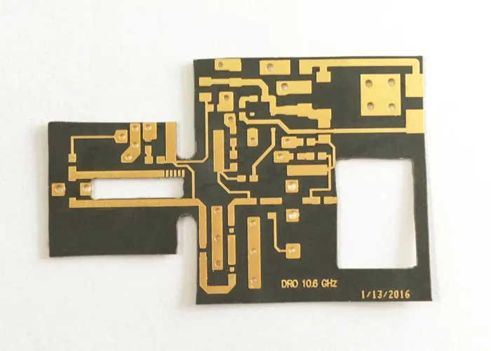

RT/duroid 5880 offers a dissipation factor of 0.0009 at 10 GHz and a dielectric constant of 2.20 ± 0.02 — among the lowest loss and tightest tolerance available in a commercial laminate. It is also glass-microfibre-reinforced PTFE, which means it is soft, chemically inert, dimensionally unstable under heat, and unforgiving of any fabricator treating it like epoxy. Understanding why it is difficult tells you what to specify and what to ask.
Why PTFE resists everything you want to do to it
Copper will not stick to it
PTFE is chemically inert, which is exactly why it performs so well electrically and exactly why plating adheres poorly. Hole walls must be surface-activated before any copper goes down, using either sodium-naphthalene etch or a plasma cycle tuned for fluoropolymers. Skip or under-run this step and the board passes electrical test, passes visual inspection, and then fails during thermal cycling as the barrel separates from the wall.
This is the single most important process question to ask a prospective supplier. Sodium etch is effective but involves aggressive chemistry and leaves a visible brown discoloration on the hole wall. Plasma is cleaner and more controllable but requires equipment and a validated recipe. Either is acceptable; subcontracting the step to a third party is where schedules slip and consistency suffers, because the fabricator no longer controls the variable that determines whether your boards survive.
It moves under heat
The z-axis coefficient of thermal expansion for RT/duroid 5880 is dramatically higher than that of epoxy laminates — in the region of 237 ppm/°C compared with roughly 50 to 70 for FR-4. During lamination and again during assembly reflow, the material expands and contracts far more than the copper bonded to it. On a two-layer board this is manageable. On a six-layer PTFE build, layer-to-layer registration becomes the dominant yield constraint, and any fabricator quoting the same registration tolerance they quote for FR-4 has not built one.
The same expansion drives plated barrel stress. A via that survives a single reflow may crack after three, because each cycle works the copper barrel against a substrate expanding many times faster than it does. This is why plating thickness and hole-wall preparation matter more here than on conventional material, and why thermal cycling belongs in qualification rather than in the optional column.
It is physically soft
The material scratches, dents and creases under handling that FR-4 shrugs off. A fingernail mark on the copper surface of a microwave board can become a measurable discontinuity. Storage, panel handling and inspection procedures all matter more here than on any other laminate, which is one reason experienced shops keep PTFE work physically separated from their general production flow rather than running it down the same line on a Tuesday.
Drilling and hole quality
PTFE does not smear the way epoxy does; it tears and stretches. Drill parameters that produce clean holes in FR-4 will produce ragged, tapered holes here. What a competent shop does differently:
- New or lightly used drill bits, retired far earlier than on epoxy work.
- Reduced surface speed with adjusted chip load to cut rather than melt the resin.
- Entry and backup material chosen for soft substrates rather than standard aluminium foil practice.
- Desmear chemistry adapted for fluoropolymer, since the standard permanganate cycle is designed for epoxy and does not clean PTFE hole walls the same way.
- Conservative drill aspect ratio, typically pulled back from the 10:1 commonly quoted on FR-4.
Ask to see a cross-section micrograph of a plated hole from a previous PTFE job. A shop that runs this material routinely will have one available without a long delay, and the image tells you more about their process control than any capability list.
Multilayer construction and bonding
Bonding PTFE layers together is a separate problem from fabricating a single core. Standard FR-4 prepreg will not bond reliably to a fluoropolymer surface, so the construction depends on a compatible bonding film — 2929 bondply being a common choice for RT/duroid constructions, selected because its dielectric properties sit close enough to the core material that the composite behaves predictably.
An alternative is fusion bonding, in which PTFE layers are bonded to each other under high temperature and pressure without an intermediate adhesive. This produces the most electrically homogeneous result and avoids introducing a different dielectric into the stackup, but it demands press capability, tooling and process control that a minority of shops possess. If your design requires it, confirm the capability specifically rather than assuming a supplier handling single-layer PTFE can also fusion bond.
Either way, keep the stackup symmetrical. Asymmetric constructions in a material with this much thermal expansion warp, and a warped microwave board is difficult to assemble and impossible to characterise reliably.
Handling, storage and inspection
Because the material is soft and its electrical performance depends on surface condition, the handling procedures around a PTFE job are part of the process rather than housekeeping around it. Panels should be stored flat and interleaved rather than stacked directly, kept away from any environment where a dropped tool or a sliding panel can mark the copper, and moved with gloves throughout. Cosmetic damage on FR-4 is cosmetic; on a microwave surface it can be electrical.
Inspection also needs recalibrating. Standard automated optical inspection is tuned to catch opens, shorts and etch defects, and it will do that here perfectly well. What it will not catch is the class of defect that actually matters on a low-loss board: a subtle etch profile variation across the panel, a dent that changes local geometry, or a hole wall whose adhesion is poor but whose electrical continuity is fine. Cross-sectioning and impedance coupon data are how those get caught, which is why the coupon requirement belongs in the purchase order rather than in a follow-up email.
Set expectations on lead time as well. PTFE work generally moves more slowly than epoxy work at the same shop, partly because of the extra process steps and partly because sensible fabricators do not rush it. A quoted lead time identical to their FR-4 turnaround is worth questioning rather than celebrating.
Do you actually need 5880?
RT/duroid 5880 is frequently specified when a less difficult material would meet the requirement. Before committing, compare against the realistic alternatives.
| Laminate | Dk @10 GHz | Df @10 GHz | Consider it instead when |
| RT/duroid 5880 | 2.20 ± 0.02 | 0.0009 | Lowest loss is genuinely required |
| RT/duroid 5870 | 2.33 ± 0.02 | 0.0012 | Slightly more loss is acceptable |
| RO3003 | 3.00 ± 0.04 | 0.0010 | Dk stability over temperature matters more |
| RO4350B | 3.48 ± 0.05 | 0.0037 | Below ~20 GHz with a comfortable loss budget |
The honest test: calculate your insertion loss on RO4350B first. If the design closes with margin, the enormous reduction in fabrication risk, supplier availability and cost is worth more than the theoretical performance you leave on the table. If it does not close, move to PTFE with your eyes open and budget the schedule accordingly.
Specifying the job properly
A PTFE fabrication package needs more detail than an FR-4 one. Include the exact laminate designation and thickness, the copper foil type and weight on each side, the required surface finish with justification if it is not the shop default, the impedance targets with reference to which layers, the bonding material for multilayer constructions, and a note that pressed rather than nominal thicknesses should be reported back.
Add an explicit requirement for lot-level certificates of conformance. The ±0.02 dielectric tolerance is one of the main reasons to pay for this material, and it is only meaningful if a single lot supplies the whole run. Any competent Rogers PCB manufacturer will supply lot documentation as a matter of course; treat hesitation on this point as disqualifying rather than negotiable.
Surface finish matters more than usual
Electroless nickel immersion gold is the default finish across much of the industry, and on microwave boards it is often the wrong one. The nickel layer is ferromagnetic and comparatively lossy, and above roughly 10 GHz it adds measurable insertion loss to any trace whose current it carries. Immersion silver avoids the nickel entirely and is generally the better choice for high-frequency surfaces, with the trade-off that it requires more careful storage and handling before assembly.
Discuss this with your fabricator rather than accepting the house standard. A Rogers PCB supplier accustomed to microwave work will usually raise the finish question before you do, which is itself a useful signal about whether they understand what they are building.
Closing
RT/duroid 5880 rewards designs that genuinely need it and punishes those that specified it out of caution. The material is not the risk; the process is. Confirm the adhesion method, the drilling approach, the bonding strategy and the lot traceability before the first panel is cut, and the rest of the build is far more predictable than the material’s reputation suggests.